
Updated 27 Jan 2012 |
WIRKSWORTH Parish Records 1600-1900 |
Return to Front Page |
MENU |
Last |
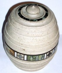
Photo 615 |
Next |
|
|
|
Barry Cooper writes: |
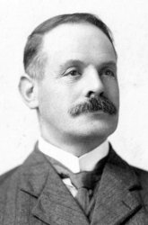
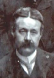
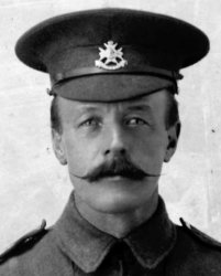
HARRISON family |
|
|
Emails |
|
Compiled, formatted, hyperlinked, encoded,
and copyright © 2010,
|
 ----
----